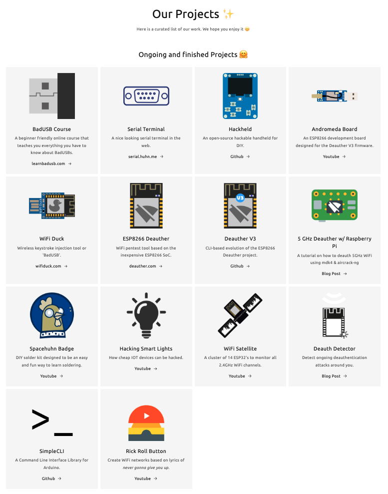
ESP8266
Description
The ESP8266 WiFi Module is a self contained SOC with integrated TCP/IP protocol stack that can give any microcontroller access to your WiFi network. The ESP8266 is capable of either hosting an application or offloading all Wi-Fi networking functions from another application processor. Each ESP8266 module comes pre-programmed with an AT command set firmware, meaning, you can simply hook this up to your Arduino device and get about as much WiFi-ability as a WiFi Shield offers (and that’s just out of the box)! The ESP8266 module is an extremely cost effective board with a huge, and ever growing, community. What is ESP8266 and what we can do with this tool PROBE SPAM. Probe spamming refers to spamming probe requests. When a WiFi enabled device eg. a phone has WiFi turned on, but is not connected to a WiFi network, it’ll openly broadcast the SSIDs (network names) of all the networks it has previously connected to in an attempt to connect to one of them. We refer to these broadcasts as probe requests Additionally, probe requests include your device’s unique MAC address, meaning probe requests can be used to track you. A probe spam simply spams these probe requests using the SSIDs specified. This can be used to confuse WiFi trackers. BEACON SPAM or BEACON FLOODING. Beacon spam refers to spamming beacon frames. A beacon frame is simply a packet of information that an Access Point sends out, telling nearby devices the network exists Using a deauther you can spam these beacon frames, effectively creating ghost networks. These ghost networks cannot be connected to, they do not exist.
- Localized Open SSID\Beacons Swarming - Reverse KARMA.
- notice that in BEACON SPAM attack the APs names are not random names and if we make it legitimate name like Starbuks, Android AP etc.. in order to brute foce the a device connect to one of the SSIDs in this way we know that he connected to this network in the past and its in trusted network and we can use this in order to lunch an Evil Twin attack and make this device connect to us this is called reverse KARMA attack and we can do it either using MDK3 or ESP8266
- The basic concept for a localized open SSID swarming attack is to create the appearance of many available open networks, selected from a list of common open network names found in a victim's geographic area using Wigle Wifi This fake AP attack will cause any nearby device which has connected to a network with the same name (SSID) before to attempt to connect, revealing its true MAC address and populating a list of open essentially the device trusts.
- This information allows an attacker to use these trusted open networks stored on the phone to unmask or connect to the target's device at will, simply by creating a fake AP with the same name and preventing the victim from connecting to other networks. Once these network names are identified, the attacker can use these them to take over the victims data connection with a MITM attack without any warning or prompt on the device.
- We made the assumption that the most popular SSIDs are open hotspots that do not use encryption. Therefore, the APs we broadcast were configured to be open hotspots. Although airbase-ng supports the creation of multiple SSIDs, our experiments revealed that it does not properly handle a large number of SSIDs. Therefore, we limited our attack to a reasonable number of SSIDs, i.e., 5 SSIDs.
- By using a modified version of Spacehuhn's Beacon Spammer, we're able to raise the number of advertised SSIDs to hundreds, improving our chances of finding trusted networks saved on nearby devices. Mathy went on to show that a few very popular SSIDs go a long way, meaning many devices will react to a few popular SSIDs. This means swarming devices with hundreds of popular SSIDs may be overkill, but it should work just fine. DEAUTHING NETWORKS or DIASSOC NETWORKS. Wi-Fi deauthentication attack and Wi-Fi disassociation attack are two attacks in which an attacker spoofs the MAC address of a victim's device and sends a deauthentication frame or disassociation frame to an access point Deauthing a network means to forcibly disconnect all the devices connected to a network. This is possible as the Management frames used to administrate a WiFi connection are unencrypted. So a 3rd party can inject false Management Frames into a network, disconnecting clients. Deauthing should not be confused with signal jamming. Think of jamming as shouting at the top of your voice to stop two people having a conversation. Deauthing is like putting on a fake moustache and bad accent, pretending to be one of the two people, and then just ending the conversation. RADIO JAMMING. Radio jamming is the deliberate jamming, blocking or interference with wireless communications. In some cases jammers work by the transmission of radio signals that disrupt communications by decreasing the signal-to-noise ratio. The concept can be used in wireless data networks to disrupt information flow.
Technical Specifications
- Processor: L106 32-bit RISC microprocessor core based on the Tensilica Xtensa Diamond Standard 106Micro running at 80 MHz[5]
- Memory:
- External QSPI flash: up to 16 MiB is supported (512 KiB to 4 MiB typically included)
- IEEE 802.11 b/g/n Wi-Fi
- 16 GPIO pins
- SPI
- I²C (software implementation)[6]
- I²S interfaces with DMA (sharing pins with GPIO)
- UART on dedicated pins, plus a transmit-only UART can be enabled on GPIO2
- 10-bit ADC (successive approximation ADC)
 https://www.wia.io/things/espressif-esp8266
The ESP8266 is a low-cost Wi-Fi microchip, with built-in TCP/IP networking software, and microcontroller capability, produced by Espressif Systems[1] in Shanghai, China. The chip was popularized in the English-speaking maker community in August 2014 via the ESP-01 module, made by a third-party manufacturer Ai-Thinker. This small module allows microcontrollers to connect to a Wi-Fi network and make simple TCP/IP connections using Hayes-style commands. However, at first, there was almost no English-language documentation on the chip and the commands it accepted.[2] The very low price and the fact that there were very few external components on the module, which suggested that it could eventually be very inexpensive in volume, attracted many hackers to explore the module, the chip, and the software on it, as well as to translate the Chinese documentation.[3] The ESP8285 is a similar chip with a built-in 1 MiB flash memory, allowing the design of single-chip devices capable of connecting via Wi-Fi.[4] These microcontroller chips have been succeeded by the ESP32 family of devices. https://en.wikipedia.org/wiki/ESP8266
Power NodeMcu Module
There are several ways to supply power to the module:
- Supply 5-18 V through Vin;
- 5V via USB or VUSB pin;
- 3.3V via 3V pin.
Benefits of NodeMcu v3
- The presence of a UART-USB interface with a micro USB connector makes it easy to connect the board to a computer.
- The presence of flash memory at 4 MB.
- Ability to update firmware via USB.
- Ability to create scripts on LUA and save them in the file system.
Disadvantages of the NodeMcu module
The main disadvantage is the ability to execute only LUA scripts located in RAM. This type of memory is small, the volume is only 20 KB, so writing large scripts causes a number of difficulties. First of all, the whole algorithm will have to be divided into linear blocks. These blocks must be written to separate system files. All of these modules are executed using the dofile operator. When writing, you must follow the rule – when exchanging data between modules, you need to use global variables, and when calculating inside modules, you need to use local variables. It is also important to call the collectgarbage function (garbage collector) at the end of each script you write.
Nodemcu v3 datasheet
nodemcu V3 module has 11 general-purpose I/O pinout. In addition, some of the conclusions have additional functions:
- D1-D10 – outputs with pulse-width modulation;
- D1, D2– pins for the I²C / TWI interface;
- D5 – D8 – pins for the SPI interface;
- D9, D10 – UART;
- A0 – input from the ADC. Image unavailable: nodemcu-pinout.jpg
How do I connect to NodeMCU?
To get started with NodeMcu, you need to connect the board to the computer. The first step is to install the CP2102 driver and open the Arduino IDE. Then you need to find in the “File” – “Settings” and in the “additional links for the board manager” window insert the link http://arduino.esp8266.com/versions/2.3.0/package_esp8266com_index.json Image unavailable: nodemcu-drivers.jpg After that, in the menu “documents” – “board” “board manager” select “esp8266” and install the latest version. After the done actions in the menu “tools” – “board” you need to find NodeMCU. After all the necessary data is installed and copied, you can start working.
Nodemcu esp8266 examples
An example of connecting an LED to NodeMCU schematicThe schematic diagram of the connection is shown in the figure. Image unavailable: nodemcu-v3-schematic.jpg The final layout of the layout is as follows: Image unavailable: nodemcu-led-pin.jpg The board itself runs on 3.3 V, so you need to use a resistor to connect the LED. In this example, a 65-ohm resistor is taken for the red LED. In a similar way, a photodiode is also connected to the board: Image unavailable: nodemcu-led.jpg The NodeMCU V3 board can also be used for IR control. To control you need a remote control with an IR receiver and the platform itself. The infrared receiver is connected as shown below: Image unavailable: nodemcu-board.jpg
Firmware for esp8266 NodeMcu
The platform is loaded with the standard Node MCU firmware, in which the Lua language interpreter is integrated. Using Lua commands, you can do the following:
- Connect to a Wi-Fi access point;
- Work as a Wi-Fi access point;
- Switch to deep sleep mode to reduce energy consumption;
- Turn on or off the LED on the GPIO16 output;
- Perform various operations with files in flash memory;
- Search for an open Wi-Fi network, connect to it;
- MAC address output;
- Manage user timers. For programming NodeMCU, you can use the Arduino IDE or the SDK development kit – ESPlorer. This complex has several differences:
- It can work on many different platforms;
- It has support for multiple open files;
- Allows highlighting the Lua language code;
- The ability to smartly send files;
- The ability to support several types of firmware at the same time. To ensure correct and stable operation, you need to update the firmware to the latest version. There are several upgrade methods – cloud service, Docker Image, and compilation on Linux. Each of these methods has its pros and cons. The simplest and most understandable is the first method. Collecting firmware in the cloud service Cloud service has a simple and convenient interface. Work begins with an email. Next, you will be prompted to select the type of firmware – stable firmware or tested. The first is used for training and creating a large number of objects, so it is recommended to choose it. The next step is to connect the necessary modules. By default, several key points have already been recorded, the rest should be included only if necessary. Then additional options are selected. Among them there is FatFS support for reading an SD card or turning on debugging mode. After the start of the assembly, a letter will arrive in the mail signaling the start of the process. After a while, the second letter will come – it will be offered to choose the version of float (fractional numbers) or integer (integers). After clicking on the received link, you will need to download the bin file and place it in Resources – Binaries. The nodemcu_integer_0.9.5_20150318.bin file will be located there, which must be deleted. As a result, the contents of the folder will look as follows. Image unavailable: nodemcu-firmware.jpg
NodeMcu Firmware Update
For the correct and stable operation of the board, you need to overwrite esp_init_data_default.bin. You can download it on the official website. The necessary file must be put back into the NodeMCU Flasher firmware system along the Resources – Binaries path, having previously deleted the old file from it. Then you can connect NodeMCU and proceed with the upgrade. First you need to change the settings – in NodeMCU Flasher, in the Config tab, you need to select the assembled firmware file instead of INTERNAL://NODEMCU. Image unavailable: nodemcu-update.jpg Leave the rest unchanged, go to Operations and click Flash. As soon as the firmware finishes, you need to switch to Config again and specify the path esp_init_data_default.bin in the first line. The address where you want to move this file is also indicated. For NodeMCU, select address 0x3FC000. After that, you need to return to Operations again and click Flash. After that, you need to reformat the entire file system. To do this, run ESPlorer, be sure to set the exchange speed to 115200 and restart NodeMCU. After all the above steps there will be a new firmware version. The debug board is completely reflashed and ready to work. Short description of the Lua languageLua has a simple syntax and powerful data description constructs based on arrays and extensible semantics. This powerful programming language is used to create software, expand various games. Unlike other languages, Lua has more flexible and more powerful designs. Flashing LED on LuaYou can consider the simplest scheme – blinking LED. This example will help you learn how to work with GPIO pins. The LED must be connected as shown in the diagram. Image unavailable: nodemcu-board.jpg Then you need to write the following sketch to the left window of ESPlorer:
pin_number = 1
gpio.mode (pin_number, gpio.OUTPUT) //setting the operating mode to the output
gpio.write (pin_number, gpio.HIGH) //high level setting
gpio.write (pin_number, gpio.LOW) //low level setting
gpio.serout (1, gpio.HIGH, {+990000,990000}, 10, 1) //set the LED to blink 10 times